


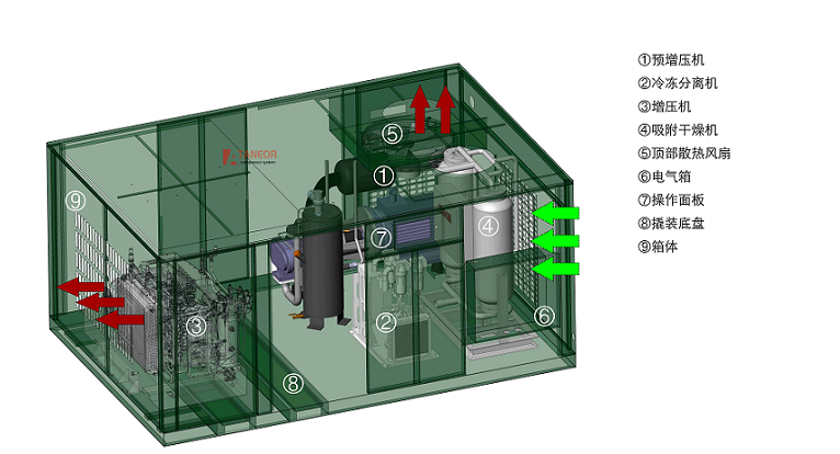
This unit is required to achieve low‑noise, high‑pressure and low‑dew‑point performance, with an integrated cabinet‑type structure for easy mobility. To satisfy the above‑mentioned specifications, the unit consists of a pre‑booster compressor, a booster compressor, an inter‑stage refrigeration separator and a post‑stage adsorption dryer.
This solution adopts a screw compressor for pre‑boosting, taking advantage of its compact size, low noise and long maintenance interval. A piston compressor is used for high‑pressure boosting to meet high‑pressure requirements.
Screw compressors feature high rotational speed, compact footprint and low noise. With a front‑mounted pre‑booster, the intake flow and installed power of the piston compressor are substantially reduced, bringing benefits including low vibration, low noise, low heat rejection and capability for long‑duration operation.
The inter‑stage refrigeration separator fully separates free moisture in the air, greatly lowering the dew‑point before air enters the booster compressor.
The inter‑stage refrigeration separator ensures the air temperature at the booster inlet is lower than ambient temperature. According to thermodynamic principles, effective inter‑stage cooling in multi‑stage boosting substantially improves the unit’s thermal efficiency and protects the high‑pressure piston compressor from free‑moisture damage.
The combined unit enables even distribution of compression heat inside the cabinet, achieving satisfactory heat dissipation performance.
In summary: this solution makes full use of merits and avoids drawbacks of the two different compressor types. By adopting respective strengths and eliminating weaknesses, and optimizing layout of main and auxiliary equipment, the unit fulfils high‑performance specifications.
Overall unit dimensions: less than 3000 × 2000 × 1700 mm; total weight: less than 2600 kg. Design service life of compressor and components: no less than 15 years.
Medium: Air Structure: Air‑cooled Nominal volume flow: 1.5 m³/min Suction pressure (Gauge): Atmospheric pressure Discharge pressure (Gauge): 1.6 MPa Suction temperature: ≤ 40 ℃ Delivery‑gas temperature: ≤ 20 ℃ Compressor rotational speed: 3000 r/min Transmission: Coupler direct‑drive Control mode: Variable‑frequency Lubrication: Oil‑injected Noise: ≤ 68 dB(A) Installed motor power: 15 kW / 3000 rpm Overall dimensions (L × W × H): approx. 1200 × 1050 × 1300 mm Weight: approx. 600 kg
Medium: Air Structure: Air‑cooled Compression stages: Two‑stage compression Cylinder bore of each stage: 1st‑stage 40 mm; 2nd‑stage 20 mm Nominal volume flow: 1.5 m³/min Suction pressure (Gauge): 1.6 MPa Discharge pressure (Gauge): 20.0 MPa Suction temperature: ≤ 20 ℃ Delivery‑gas temperature: ≤ 200 ℃, ≤ 65 ℃ (after cooling) Compressor rotational speed: 900 r/min Transmission: Belt drive Control mode: Auto‑stop at set pressure (low‑pressure auto‑restart supported); over‑pressure alarm and shutdown; electronic automatic drain. Lubrication: Splash lubrication Lubricating‑oil consumption: 50 g/h Noise: ≤ 85 dB(A) Installed motor power: 15 kW / 980 rpm Piston stroke: 115 mm Overall dimensions (L × W × H): approx. 1750 × 1050 × 1200 mm Weight: approx. 1000 kg
Crankcase Assembly Side covers for disassembly and inspection and an oil sight glass are arranged on both sides of the crankcase. A bearing housing and front bearing cover are fitted at the front power‑connection end. A fan bracket above the rear bearing cover supports the fan assembly. Cylinder‑mounting planes are cast on the upper part, and a breather is installed on the top surface. The bottom of the crankcase contains dedicated compressor lubricating oil.
Crankshaft, Connecting‑rod Assembly Connecting rods are mounted on the crank throws of the crankshaft. Rolling bearings are fitted at both ends of the crankshaft. A flywheel connected to the flexible coupling is installed at the large end of the crankshaft; a pulley near the bearing at the small end drives the cooling‑fan rotation. Crankshaft lubrication is achieved by means of the oil‑sling rod of the connecting rod, which splashes oil onto the crankshaft, piston pins and other components.
Piston Assembly The piston assembly serves two cylinders for the second stage. Pistons are made of casting and aluminium alloy, each fitted with piston rings.
Cylinder Assembly Fins are provided on the outer surface of each cylinder to enlarge heat‑dissipation area. Inlet‑outlet valve assemblies, inlet‑outlet pressure sleeves and inlet‑outlet pressure caps are installed inside each cylinder head.
Inlet and Discharge Valve Assembly Inlet and discharge valves are steel‑made ring‑type valves and combined valves.
Cooler and Fan Assembly Consists of an after‑cooler and a cooling fan. The assembly is foot‑mounted on the base. A safety valve is fitted on the upper section of the cooler, and a drain valve on the lower section. A guide shroud and protective guard are arranged towards the crank‑case side. A suction‑type cooling fan is mounted in the middle; the fan assembly is secured to the crankcase via a fan bracket and driven by V‑belts from the crankshaft pulley at the crankcase end.
Refrigeration Separator Comprises air‑cooled refrigerated dryer + two‑stage filters (oil‑removal filter + water‑removal filter) Weight: approx. 200 kg
Adsorption Dryer Integrated assembly of adsorption dryer + three‑stage filters + centralized drain Treatment capacity: 1.5 m³/min Working pressure: ≤ 200 bar Inlet / outlet connection: NPT1/2 internal thread Outlet atmospheric dew‑point: ≤ ‑55 ℃ Purge‑gas consumption: ≤ 5 % Weight: approx. 300 kg
Cabinet and Heat‑dissipation System (1) Openable doors are arranged on both long sides of the cabinet for operator access for routine inspection, with a service aisle in the middle. (2) Cooling air enters through side air‑intake grilles of the cabinet and is discharged via cooling fans fitted on the pre‑booster and booster compressors.
Skid‑mounted Chassis Assembly The whole unit is mounted on a steel chassis fitted with casters underneath for convenient mobility.
Start‑stop push‑buttons are provided on the operation panel to control both the pre‑booster and booster compressor simultaneously.
Automatic unloading of the compressor upon reaching set pressure.
Automatic shutdown of the compressor under over‑pressure conditions.
The user may adjust the set‑point within the rated pressure range as required.
 |
TELEPHONE |
 |
公司地址:18 Kailu Avenue, Jianshe Road, Liangxiang, Fangshan District, Beijing |
 |
邮箱:info@taneor.com |
 |
手机:(+86)13601381607 |

