


The major gas‑end components of the reciprocating compressor (Figure 4) are:
Cylinder Body
Cylinder Head
Piston and Piston Rod
Suction Valve
Discharge Valve
Piston‑rod Packing
Suction and Discharge Gas Jackets

Figure 4: Components of a Reciprocating Compressor
The piston reciprocates inside the cylinder of a reciprocating compressor. To reduce repair costs, the cylinder may be fitted with a liner or sleeve. Wear normally occurs on the cylinder or liner at the contact area where piston rings rub against it. Due to the weight of the piston, wear is generally more severe at the bottom of horizontal cylinders.
The ends of the cylinder are equipped with removable heads, which may incorporate water/liquid jackets for cooling. One end is referred to as the cylinder‑head end, and the other as the crank end. The crank end contains packing (a set of metallic packing rings) to prevent gas leakage around the piston rod.
The piston moves back and forth to draw in and compress gas. It pushes gas into the discharge line during the compression stroke.
For low‑speed (up to 330 rpm) and medium‑speed reciprocating compressors (330‑600 rpm), pistons are normally made of cast iron.
Cast‑iron pistons up to 7 inches in diameter are manufactured from solid bars. Those over 7 inches in diameter are usually hollow (to reduce cost).
Stainless‑steel pistons are sometimes used for compressing oxygen and other gases that must remain lubricant‑free.
When a reciprocating compressor reaches operating temperature, the piston and piston rod expand to a greater extent than the cylinder liner/cylinder.
Typically, one‑third of the piston end clearance is allocated at the crank end, and two‑thirds of the end clearance at the cylinder‑head end.
Piston rings provide sealing to prevent or minimize leakage across the piston and cylinder liner. Metallic piston rings may be one‑piece, split, or multi‑segment. The gap in the rings allows them to expand when the compressor reaches operating temperature. Heavy‑duty piston rings are sometimes fitted with expandable rings made of bronze, babbitt alloy or Teflon. Lubrication is mandatory for metallic rings. When lubricants are not permitted for the process gas, Teflon rings are sometimes employed to support the piston.
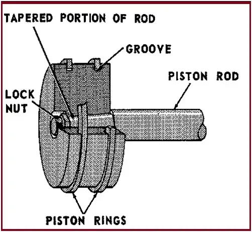
Fig. 5: Typical Arrangement of Piston Rings
The piston rod is fastened to the piston by means of a special lock nut to prevent loosening. The rod surface has a suitable finish designed to minimize wear in the sealing area. Grooves for piston rings and guide rings are provided on the piston.

Fig. 6: Typical Arrangement of Piston Rod and Piston
The piston‑rod packing consists of a series of cups, each holding several sealing rings arranged side‑by‑side. The rings are made of multiple segments held together by springs. The complete packing assembly is held in position by stud bolts. Internal passages are provided for cooling, gas recovery and lubrication of the piston‑rod packing.
Oil wiper rings are arranged to prevent oil entrained by the piston rod from leaking out of the crankcase. The scraped‑off oil returns to the crankcase sump.
These allow gas to enter the piston during the suction stroke and permit gas to flow out to the discharge line during the compression stroke.
 |
TELEPHONE |
 |
Address:18 Kailu Avenue, Jianshe Road, Liangxiang, Fangshan District, Beijing |
 |
Email:info@taneor.com |
 |
Tel:(+86)13601381607 |

